كيف تعمل خيوط التي المجلفنة مع التركيبات؟

تعمل خيوط التي المجلفنة مع التركيبات في أنظمة السباكة والتوصيلات بطريقة فعالة تضمن التوصيل السليم والمقاومة للتآكل. إليك كيفية عملها:

1. المكونات الأساسية

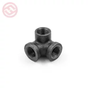
  • خيوط التي المجلفنة: هي خيوط معدنية (عادةً من الفولاذ) يتم تغليفها بطبقة من الزنك لتحسين مقاومتها للتآكل.
  • التركيبات: تشمل المحولات، الصمامات، والموصلات التي تُستخدم لربط الخيوط معًا.

2. عملية الربط

  • التوصيل: يتم لف خيوط التي المجلفنة بشكل لولبي لتسهيل الربط مع التركيبات. الخيوط تكون مصممة لتناسب الخيوط الداخلية للتركيبات.
  • الضغط: عند ربط الخيوط بالتركيبات، يتم تطبيق الضغط لخلق اتصال محكم يمنع التسرب.

3. المقاومة للتآكل

  • الطلاء المجلفن: يساعد الطلاء الزنكي في حماية الخيوط من التآكل الناتج عن الرطوبة والعوامل البيئية، مما يعزز عمر الخدمة.
  • تآكل أقل: بفضل المجلفن، تكون الخيوط أكثر مقاومة للتآكل مقارنةً بالخيوط غير المعالجة، مما يجعها مثالية للاستخدام في التطبيقات الخارجية أو في البيئات الرطبة.

4. التحمل والمرونة

  • الصلابة: توفر خيوط التي المجلفنة صلابة كافية لتحمل الضغوط العالية في الأنظمة المختلفة.
  • المرونة: تسمح التصميمات بمرونة معينة، مما يساعد في التكيف مع التغيرات في درجة الحرارة والضغط.

5. التطبيقات

  • تُستخدم خيوط التي المجلفنة في مجموعة متنوعة من التطبيقات، بما في ذلك:
    • أنظمة المياه والصرف الصحي.
    • أنظمة الغاز.
    • التطبيقات الصناعية.

ملخص

تعمل خيوط التي المجلفنة مع التركيبات من خلال توفير ربط محكم ومقاومة للتآكل، مما يضمن أداءً موثوقًا في مختلف التطبيقات. الطلاء الزنكي يعزز من عمر الخدمة، بينما تساهم التركيب اللولبي في تسهيل عملية الربط.

وصلات مجلفنة

How does a filter press work?

A filter press is a piece of equipment used to separate solids from liquids, typically in industrial or laboratory settings. It works on the principle of pressure filtration, where liquid (usually a slurry) is forced through a filter medium to separate the solid particles.

Here’s how does a filter press work step-by-step:

1. Slurry Introduction

  • The slurry (a mixture of solid and liquid) is pumped into the filter press through an inlet manifold.
  • The slurry enters into the chambers formed by a series of filter plates that are stacked together. Each plate is covered with a filter cloth that acts as the medium through which the liquid will pass.

2. Building of Cake

  • The plates are tightly pressed together using hydraulic or mechanical pressure, forming a series of sealed chambers.
  • As the slurry enters the chambers, the liquid (often called the filtrate) passes through the filter cloths, leaving the solid particles behind.
  • The solids collect on the cloth and form a filter cake. The filter cake becomes thicker as more slurry is introduced.

3. Filtration Process

  • The liquid passes through the cloths and out of the press, often through a manifold system that channels the filtrate away.
  • The pressure applied helps speed up the filtration process, forcing the liquid to pass through the filter medium, while the solid particles are trapped.
  • The pressure within the filter press may be supplied by a hydraulic system or through manual tightening, depending on the design of the press.

4. End of Filtration

  • Once the filter cake has built up to the desired thickness, and the liquid has been sufficiently separated, the filtration process ends.

5. Cake Discharge

  • The press is then opened by releasing the pressure. The filter plates are separated, and the solid cake (the accumulated material) is removed.
  • In some cases, the press may be washed to remove any remaining liquid trapped in the cake before discharging it.

6. Cleaning and Reuse

  • After discharge, the filter cloths can be cleaned to remove any residue, and the press is ready to be reused for another batch of filtration.

Key Components:

  1. Filter Plates: These are stacked together and are the structure that holds the filter cloth and slurry.
  2. Filter Cloths: These are attached to the filter plates and act as the filtering medium. They are made from materials like polyester or polypropylene.
  3. Manifold: The system used to distribute slurry into the filter press and collect the filtrate.
  4. Hydraulic System: Used to apply the necessary pressure to the plates, ensuring tight sealing and effective filtration.

Types of Filter Presses:

  1. Plate and Frame Filter Press: The classic design with individual frames and filter plates. It’s used for batch processes.
  2. Membrane Filter Press: Similar to the plate and frame design, but with a membrane behind each filter plate. The membrane can be inflated with air or liquid to help release the filter cake more easily.
  3. Automatic Filter Press: Includes automated systems for cake discharge, cloth washing, and sometimes even for adjusting pressures or flow rates.

Applications:

  • Mining: Separating valuable minerals from ore or separating water from tailings.
  • Wastewater Treatment: Removing sludge from treated water.
  • Food & Beverage Industry: For filtering oils, juices, and other liquid products.
  • Chemical Processing: Removing solid particles from chemical solutions.

In summary, a filter press operates by using pressure to force a slurry through a filter medium, separating solids from liquids. The solid particles form a cake that can be removed, and the filtered liquid is collected for further use or disposal.

What is the role of a greenhouse in organic farming?

A greenhouse china plays a significant role in organic farming by providing a controlled environment that enhances the growth and productivity of organic crops.

Here are some key functions and benefits of greenhouses in this context:

1. Controlled Growing Conditions

  • Temperature and Humidity Regulation: Greenhouses allow farmers to maintain optimal temperature and humidity levels, which can enhance plant growth and extend the growing season.
  • Protection from Weather Extremes: They shield crops from harsh weather conditions, such as heavy rain, frost, and strong winds, reducing the risk of crop loss.

2. Extended Growing Seasons

  • Year-Round Production: Greenhouses enable organic farmers to grow crops throughout the year, even in off-seasons, which can lead to increased yield and profitability.
  • Early Planting and Late Harvesting: Farmers can start planting earlier in the spring and continue harvesting later into the fall or winter.

3. Pest and Disease Management

  • Reduced Pest Infestation: The enclosed environment of a greenhouse can minimize exposure to pests, allowing for easier management and reducing the need for chemical pesticides.
  • Integrated Pest Management (IPM): Organic farmers can use beneficial insects and other natural methods to control pests without resorting to synthetic chemicals.

4. Soil and Nutrient Management

  • Soilless Cultivation: Many organic greenhouses utilize hydroponic or aquaponic systems, allowing for efficient nutrient delivery without soil, which can reduce soil-borne diseases.
  • Compost and Organic Fertilizers: Greenhouses can facilitate the use of compost and organic fertilizers, promoting healthy soil biology and nutrient cycling.

5. Water Conservation

  • Efficient Water Use: Greenhouses can incorporate drip irrigation or other efficient watering systems to minimize water waste and ensure that plants receive the right amount of moisture.
  • Rainwater Harvesting: Some greenhouses are designed to collect and reuse rainwater, further enhancing sustainability.

6. Diverse Crop Production

  • Variety of Crops: Greenhouses allow for the cultivation of a wide range of organic crops, including fruits, vegetables, and herbs, regardless of the outside climate.
  • Specialty Crops: Farmers can grow high-value specialty crops that may not thrive in the local outdoor conditions.

7. Research and Education

  • Experimental Growing: Greenhouses provide a controlled setting for organic farmers to experiment with new varieties, growing techniques, and organic practices.
  • Educational Opportunities: They serve as demonstration sites for teaching sustainable agricultural practices to students, farmers, and the community.

8. Market Advantage

  • Higher Market Value: Organic produce grown in greenhouses can often command higher prices due to its freshness and quality, offering farmers a better return on investment.
  • Local Food Production: Greenhouses contribute to local food systems, reducing transportation costs and providing fresh produce to nearby markets.

Conclusion

In summary, greenhouse manufacturer play a crucial role in organic farming by enhancing crop production, providing a controlled environment, and promoting sustainable practices. They enable farmers to grow high-quality organic produce efficiently while minimizing environmental impact, making them an invaluable tool in modern organic agriculture.

How do butterfly valve exhaust system work in the instrumentation industry?

In the instrumentation industry, butterfly valves are commonly used in exhaust systems for their efficiency, compact design, and ability to control flow precisely.

Here’s how butterfly valve exhaust system work and their applications:

1. Basic Operation

  • Flow Control: Butterfly valves consist of a disc (the “butterfly”) that rotates around a central axis to open or close the valve. When the disc is parallel to the flow, the valve is open; when perpendicular, it is closed.
  • Quick Response: The design allows for rapid opening and closing, making it suitable for systems that require quick response times.

2. Integration in Exhaust Systems

  • Exhaust Management: In instrumentation systems, butterfly valves can be employed to manage the exhaust of gases, vapors, or other emissions from equipment and processes.
  • Pressure Control: They help maintain optimal pressure levels within the system by regulating the flow of exhaust, ensuring that pressure does not exceed safe limits.

3. Control Mechanisms

  • Actuators: Butterfly valves can be operated manually or automatically using electric, pneumatic, or hydraulic actuators.
    • Electric Actuators: Provide precise control and integration with automated systems.
    • Pneumatic Actuators: Offer fast operation and are commonly used in process control systems.

4. Applications in Instrumentation

  • Ventilation Systems: Used to control airflow in ventilation and fume extraction systems, ensuring proper air quality and safety.
  • Process Control: In manufacturing processes, they regulate the flow of exhaust gases, helping to maintain process efficiency and safety.
  • Environmental Compliance: Ensure that exhaust emissions meet regulatory standards by controlling the release of pollutants.

5. Advantages

  • Compact Design: Butterfly valves are space-saving compared to other valve types, making them ideal for tight installations.
  • Low Pressure Drop: They provide minimal resistance to flow when fully open, which is beneficial for maintaining system efficiency.
  • Cost-Effective: Generally more affordable than other valve types with similar capabilities, making them a popular choice.

6. Considerations

  • Material Selection: Choosing the right materials is crucial, especially in corrosive environments. Common materials include stainless steel and various plastics.
  • Sizing and Pressure Ratings: Proper sizing is essential to ensure effective operation and avoid issues like cavitation or excessive wear.

Conclusion

In summary, exhaust pipe butterfly valve play a critical role in the exhaust systems of the instrumentation industry by providing efficient and effective flow control. Their quick operation, compact design, and adaptability to various control mechanisms make them a preferred choice for managing exhaust in various applications, from manufacturing to environmental compliance.

what are diapers made out of

Diapers are made from a combination of materials designed to provide comfort, absorbency, and leak protection.

Here’s a breakdown of the primary components for what are diapers made out of:

1. Top Sheet

  • Material: Typically made of non-woven fabric, often polypropylene or polyethylene.
  • Function: The top sheet is the layer in contact with the baby’s skin. It is designed to be soft, breathable, and allow moisture to pass through to the absorbent core while keeping the surface dry.

2. Absorbent Core

  • Material: A combination of fluff pulp (wood pulp) and superabsorbent polymer (SAP).
  • Function: The absorbent core is responsible for soaking up and retaining moisture. SAP can absorb many times its weight in liquid, helping to keep the diaper dry.

3. Back Sheet

  • Material: Usually made from polyethylene or another waterproof material.
  • Function: The back sheet prevents leaks by providing a barrier that keeps moisture from escaping the diaper.

4. Elastic Components

  • Material: Elastic bands made from materials like rubber or spandex.
  • Function: These are used around the leg openings and waist to provide a snug fit, helping to prevent leaks and ensuring comfort.

5. Adhesives

  • Material: Various types of adhesives are used in the construction of the diaper.
  • Function: Adhesives bond the different layers of the diaper together and secure components like the fasteners.

6. Fasteners

  • Material: Hook-and-loop fasteners (similar to Velcro) or adhesive tabs.
  • Function: These allow for easy adjustments and secure fastening of the diaper around the baby.

7. Frontal Tape

  • Material: Often made from the same materials as the back sheet.
  • Function: Provides an additional layer of security to keep the diaper in place.

8. Wetness Indicator

  • Material: Special dyes or inks that change color.
  • Function: Some diapers have a wetness indicator that changes color when the diaper is wet, alerting caregivers to a change.

Conclusion

Diapers are composed of multiple layers and materials, each serving specific functions to provide comfort, absorbency, and protection. The combination of these materials ensures that diapers effectively manage moisture and maintain skin health for infants and toddlers.

How do you prepare a transformer for turn ratio testing?

Preparing a transformer for turns ratio testing involves several important steps to ensure accurate measurements and safe operation.

Here’s a comprehensive guide:

1. Safety Precautions

  • De-energize the Transformer: Ensure that the transformer is completely de-energized and isolated from the power supply to prevent electrical hazards.
  • Lockout/Tagout (LOTO): Implement lockout/tagout procedures to ensure that the transformer cannot be accidentally energized during testing.

2. Gather Necessary Equipment

  • Test Equipment: Obtain a turn ratio of transformer formula tester or a suitable multimeter with turns ratio testing capabilities.
  • Connection Leads: Prepare appropriate connection leads and accessories for the test.
  • Personal Protective Equipment (PPE): Wear appropriate PPE, including gloves and safety glasses.

3. Inspect the Transformer

  • Visual Inspection: Check the transformer for any visible signs of damage, leaks, or corrosion. Ensure that all connections are secure.
  • Nameplate Data: Verify the transformer’s nameplate data to confirm its specifications, including voltage ratings and turns ratio.

4. Prepare Test Connections

  • Access Terminals: Ensure that you have easy access to the primary and secondary terminals of the transformer for testing.
  • Clean Connections: Clean the terminal connections to ensure low-resistance contact.

5. Set Up the Test Equipment

  • Connect the Tester: Connect the turns ratio tester to the primary and secondary terminals according to the manufacturer’s instructions.
  • Specify Test Settings: Set the tester to the appropriate test voltage and range based on the transformer specifications.

6. Perform Preliminary Checks

  • Confirm Connections: Double-check all connections to ensure they are secure and correctly configured.
  • Check Voltage Ratings: Ensure that the test voltage is within the rated limits of the transformer.

7. Conduct the Test

  • Follow Testing Procedure: Execute the turns ratio test according to the manufacturer’s instructions for the testing equipment.
  • Record Data: Document the measured turns ratio and any other relevant data.

8. Post-Test Procedures

  • Disconnect Equipment: After testing, safely disconnect the test equipment and leads from the transformer.
  • Inspect Again: Perform a final inspection of the transformer to ensure no damage occurred during testing.

9. Analyze Results

  • Evaluate Turns Ratio: Compare the measured turns ratio with the expected value from the nameplate data.
  • Identify Issues: Any significant discrepancies may indicate problems with the transformer windings or connections that require further investigation.

Conclusion

Preparing a transformer for turns ratio testing involves careful planning and execution to ensure safe and accurate results. By following these steps, you can effectively prepare for testing and maintain the integrity of the transformer.

What is the typical thread count for polyester 95 spandex 5 fabric?

The typical thread count for polyester-spandex blends, such as apolyester 95 spandex 5 fabric , can vary significantly based on the type of fabric and its intended use.

However, here are some general guidelines:

1. Common Thread Counts

  • Low to Mid Range: For most polyester-spandex blends, thread counts often range from 100 to 300. This range is common for various applications, including activewear, leggings, and casual garments.
  • Higher Thread Counts: Some premium blends may have thread counts of 300 or higher, which can enhance softness and durability, but this is less common in basic activewear fabrics.

2. Factors Influencing Thread Count

  • Fabric Type: The type of weave (e.g., plain, twill, or satin) and the specific application (e.g., clothing, upholstery) can influence the thread count.
  • Intended Use: Fabrics designed for specific uses like activewear may prioritize stretch and moisture-wicking properties over a high thread count.

3. Performance Characteristics

  • Stretch and Recovery: The presence of spandex allows the fabric to stretch and recover, which is an essential feature for active and fitted garments, regardless of thread count.
  • Comfort and Breathability: While thread count contributes to the fabric’s feel, the blend’s overall comfort is also affected by the fabric’s weave and the quality of the fibers.

Summary

In summary, a polyester 95% and spandex 5% fabric typically has a thread count ranging from 100 to 300, depending on the specific type and intended use of the fabric. Higher thread counts may be found in more premium options, but the performance characteristics are often more critical than the thread count alone.

What non-destructive testing methods are suitable for ansi 125 Grooved Adaptor Flange?

Non-destructive testing (NDT) methods are essential for evaluating the integrity of ANSI 125 grooved adaptor flanges without causing damage.

Here are several suitable NDT methods:

1. Visual Inspection (VT)

  • Description: The simplest form of NDT, visual inspection involves examining the flange for visible defects such as cracks, corrosion, and misalignment.
  • Application: Often used as the first step in any inspection process.

2. Ultrasonic Testing (UT)

  • Description: This method uses high-frequency sound waves to detect internal and surface defects. It measures the time it takes for sound waves to reflect back from flaws.
  • Application: Effective for detecting subsurface flaws and measuring wall thickness.

3. Radiographic Testing (RT)

  • Description: RT involves using X-rays or gamma rays to create images of the internal structure of the flange. It can reveal internal defects such as cracks or voids.
  • Application: Useful for complex geometries and can provide a permanent record of the inspection.

4. Magnetic Particle Testing (MT)

  • Description: This method uses magnetic fields and iron particles to detect surface and near-surface defects in ferromagnetic materials.
  • Application: Ideal for identifying cracks and other surface discontinuities.

5. Dye Penetrant Testing (PT)

  • Description: A liquid dye is applied to the surface of the flange, which penetrates any surface cracks. After a specified dwell time, excess dye is removed, and a developer is applied to draw out the penetrant and reveal defects.
  • Application: Effective for detecting surface-breaking defects on non-porous materials.

6. Eddy Current Testing (ECT)

  • Description: ECT uses electromagnetic induction to detect flaws in conductive materials. It measures changes in electrical conductivity and magnetic permeability.
  • Application: Suitable for detecting surface and near-surface defects, particularly in thin-walled flanges.

Summary

For ANSI 125 grooved adaptor flanges, suitable non-destructive testing methods include visual inspection, ultrasonic testing, radiographic testing, magnetic particle testing, dye penetrant testing, and eddy current testing. Each method has its strengths and is chosen based on the specific characteristics of the flange and the types of defects being evaluated. Regular NDT inspections help ensure the integrity and safety of the piping system.

How often should l inspect cast iron fitting for damage?

The frequency of inspecting cast iron fitting dimensions for damage can depend on several factors, including the type of application, environmental conditions, and the specific installation.

However, here are some general guidelines:

1. Regular Inspection

  • Monthly to Quarterly: For most applications, a visual inspection should be conducted monthly to quarterly. This helps identify any signs of corrosion, cracks, or leaks early on.

2. High-Stress Environments

  • More Frequent Inspections: In high-stress environments (e.g., industrial settings, areas with heavy vibration, or extreme temperatures), consider inspecting fittings more frequently, perhaps every two weeks.

3. After Significant Events

  • Post-Event Inspections: Conduct inspections after significant events such as severe weather, seismic activity, or maintenance work, as these can affect the integrity of the fittings.

4. System Changes

  • Following Modifications: If any modifications or upgrades are made to the piping system, inspect all fittings to ensure they are still secure and undamaged.

5. Annual Comprehensive Inspections

  • Detailed Inspection: At least once a year, conduct a comprehensive inspection that includes checking for signs of wear, corrosion, and mechanical integrity. This may involve more thorough testing and possibly non-destructive testing methods.

6. Maintenance Schedule

  • Include in Regular Maintenance: Integrate fitting inspections into your regular maintenance schedule to ensure they are consistently monitored over time.

Summary

Inspect ductile iron fittings dimensions regularly, typically monthly to quarterly, with more frequent checks in high-stress environments or after significant events. Conduct a detailed inspection annually and include fitting assessments in your overall maintenance plan to ensure the integrity and longevity of the system.

What specific dielectric unions are best for galvanized grooved fittings?

When selecting dielectric unions for galvanized grooved fittings, it’s important to choose unions that effectively prevent galvanic corrosion while ensuring a reliable connection.

Here are some specific types and features to consider:

1. Material Composition

  • Brass Dielectric Unions: Brass is commonly used for dielectric unions due to its excellent corrosion resistance and compatibility with both galvanized steel and copper. Look for unions specifically designed for use with galvanized fittings.
  • Plastic or PVC Dielectric Unions: These can also be effective as they inherently prevent galvanic corrosion due to their non-metallic nature. They can be used in non-pressurized applications or where chemical compatibility is ensured.

2. Dielectric Insulation

  • Integrated Insulation: Choose unions that have built-in dielectric insulation, which physically separates the metal components to prevent electrical contact and corrosion.
  • Non-metallic Sleeves: Some unions come with non-metallic sleeves that provide an additional layer of protection against galvanic corrosion.

3. Pressure Ratings

  • Match Pressure Ratings: Ensure that the dielectric union has a pressure rating compatible with the galvanized grooved fittings. This ensures that the entire system maintains integrity under operational pressures.

4. Standard Compliance

  • Industry Standards: Look for dielectric unions that meet relevant industry standards (e.g., ANSI, ASTM) for quality and performance. This ensures they are suitable for your specific application.

5. Thread Compatibility

  • Proper Thread Types: Ensure that the dielectric union has the correct thread type (NPT, BSP, etc.) to match your galvanized fittings for a secure connection.

Recommended Products

While specific product recommendations can vary, some reputable brands that manufacture dielectric unions compatible with galvanized grooved fittings include:

  • Victaulic: Known for high-quality grooved fittings and unions, check their dielectric options designed for metal piping systems.
  • Mueller Industries: Offers a variety of dielectric unions that are compatible with different piping materials.
  • NIBCO: Provides dielectric unions specifically designed for use with copper and galvanized installations.

Summary

When choosing dielectric unions for galvanized grooved fittings, prioritize materials like brass or plastic, ensure proper dielectric insulation, match pressure ratings, and comply with industry standards. Always consult manufacturer specifications to ensure compatibility and effectiveness in preventing galvanic corrosion.

Design a site like this with WordPress.com
Get started